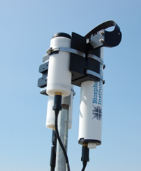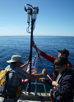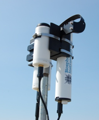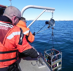
Founded in 1977Biospherical Instruments Inc. (BSI)It is an environmental monitoring instrument company that is oriented towards R&D and integrates design and production.BSI has a long history in environmental monitoring from Antarctic to Arctic, from ocean to drinking water reservoirs.
For more than 30 years, BSI's production line has focused onocean,atmosphere,Water qualityandBiological SciencesHigh quality usedOptical instrumentsThe design and production of the company is currently the leader in the field of optical instruments in the international field.BSI's products include global ultraviolet (UV) monitoring systems for land and oceans, water quality monitoring systems for drinking water sources, and optical radiators in a variety of UV and visible bands used in marine and atmospheric science.
BSI's instruments have gained wide recognition worldwide from the simplest photosynthetic effective radiation (PAR) measuring instruments to very complex radiation measurement systems for water profiles, as well as a variety of single-channel light intensity measurement sensors.Such as NASA, NOAA, EPA, WHOI, MBARI, Sea-Bird, RBR, HOBI, McLane, Teledyne, WETLabs, YSI, etc., are all loyal users of BSI.
In 1988, under the commission of the National Science Foundation (NSF), BSI began to install "Global UV monitoring network system", and BSI has been maintaining the operation of the global UV monitoring network. It was not until 2009 that this monitoring network was split into two parts: partly transferred to the U.S. Ocean and Atmospheric Administration (NOAA), and the other part is still under the responsibility of BSI..
In 2005, BSI succeeded in research and developmentMicroradiometersand obtainNASA's Business Innovation Award(SB IR).
In 2008, BSI and NASA began collaborating with the development of new, modern radiation measurement sensors to support existing and next-generation marine aqua satellite remote sensing missions.This system is calledPlanetary radiation energy optical sensor(OBodhi wipedSEnsor is forPlane ta easyRRadio AECountry of Womenhave, OSPREy), is mainly used to obtain radiation measurement data of the ocean, sky, sun and moon to meet the accuracy requirements of alternative calibration and algorithmic verification of remote sensing of ocean aqua satellites.
In 2009, BSI and the University of Chicago jointly undertake the "Natural Science Foundation"Polar Observation Network” Project, used to long-term observation of the impact of global changes on polar environment, especially UV rays.
In the field of marine optical instruments, BSI's products are industry standards.This is known from the large number of famous marine instrumentation and equipment companies purchasing optical instruments and sensors from BSI and integrating them into their own products.The following representative marine instruments and equipment companies are all loyal users of BSI:
Comesea-bird electronics, Inc.
ComeR br Ltd.
ComeFalmouthscientific, Inc.
Comeho BI labs, Inc.
ComeI robot corporation
Comeocean sensors, Inc.
ComeTeledyne RD instruments, Inc.
Comewet labs, Inc.
ComeYS II NC.
ComeMcLane research laboratories, Inc.
inSea-Bird, the most famous CTD manufacturer in the world, has purchased hundreds of sets of optical instruments and sensors from BSI., it can be said that all the optical quantum sensors on the Seabird CTD are manufactured by BSI!
BSI's new launchPortable water body optical profile measurement system C-OPSOnce launched, it was warmly welcomed by scientists around the world. Currently, its representative users includeClark University, USA,South African Institute of Science and Technology and Industry (CSIR) Institute of Natural Resources and Environment (NRE),Villefranche Marine Laboratory, France(labor at OI red ocean o graph IE's ville's anger)NASA Goddard Space Center(NASA/Goddard space center),Polish Academy of Sciences,University of Quebec, Canada(UAV site degree Quebec ARI certain ski),University of California, Santa Barbarawait.
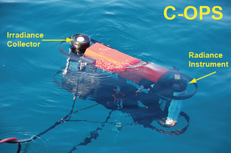
C-opsWhat is it? C-OPS is a radiation measurement system used to study the optical properties of the ocean.It consists of two radiometers: one of which measures the water bodyUpward radiance, another measurementDownward irradiance or upward irradiance.Both radiometers have19 bandsand installed inA free fall framesuperior.The frame can be optimized to settle at a lower rate in shallower offshore waters and at a higher rate in deep open ocean surfaces.Optional accessories include: a reference irradiance sensor that measures incident irradiance on water; a tape assembly "BioShade" for measuring diffusion; and a component "BioGPS" that provides coordinates and time. | 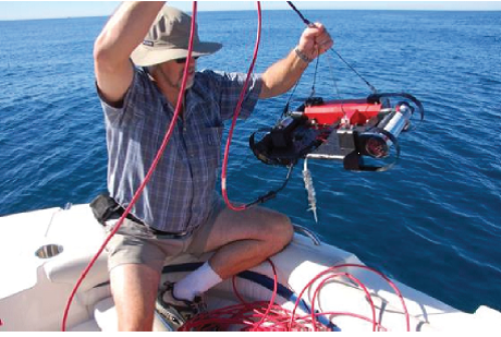 |
Why choose C-OPS?
Old optical measurement system systems do not well solve the optical complexity in shallow water, mainly due to the large instrument volume, too close to the sampling platform, or the inability to control the instrument's settlement rate well.In the new C-OPS system, none of these problems exist.
C-opsWhat's the difference?
ComeIdeal for marine aqua color research, satellite calibration and confirmation in shallow water
ComePerfect system integration allows it to work with diving equipment and water equipment to measure radiation parameters (can be applied to turbid nearshore water and clear oceanic water bodies)
ComeMeasure the radiance and irradiance of water on a vertical depth profile
ComeFast sampling frequency (15Hz), slow free fall, adjustable buoyancy, can be manually placed, and underwater up to 300 meters.
ComeDesign and research and development with NASA
ComeManufacturing based on BSI's advanced microradiometer technology
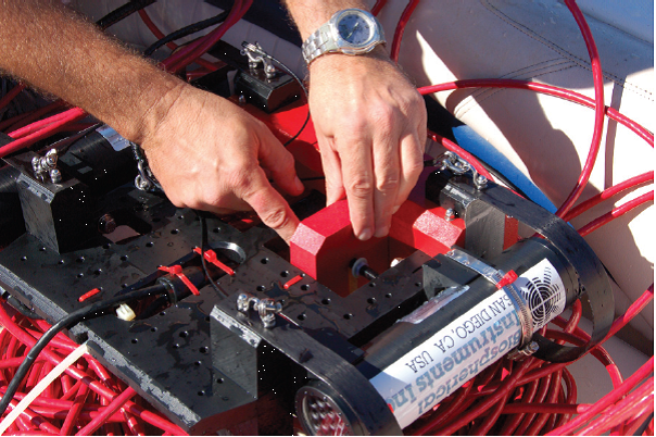
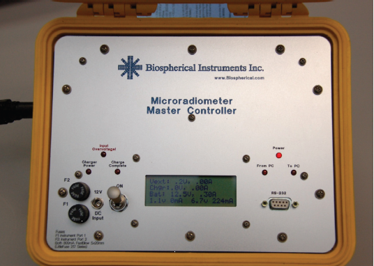
Microradiometer This new C-OPS radiation profile measurement system and all its accessories areMicroradiometer(micro radiometers)——A new method for revolutionary photodetector integration. BSI has developed a small, excellent photodetector called "Microradiometer". The microradiometer consists of a filtered photodiode with a microprocessor, a preamplifier with controllable gain, a 24-bit analog-to-digital converter and a serial port - all of which are integrated in a single penSmall circuit board size. Brass outer sleeve protects internal components and blocks external electronic noise. Although each microradiometer is a single working photodetector, multiple microradiometers can be combined to form a multi-band radiometer.The polymerizer (left) brings together several sets of microradiometers and auxiliary sensors, which also controls the data input into or output from the microradiometer.The aggregator simultaneously controls power regulation and additional sensors such as inclination, temperature, input voltage and current, and mobile storage settings (such as micro SD cards). A combination of 19 microradiometers is placed in the pressure resistant chamber, which can act as a single-machine multi-channel marine aqua sensor, and due to its compact size, one hand can easily pick up. The C-OPS buoyancy device combines air-filled buoys with rigid foam buoys.As the instrument sinks, the increased water pressure flattens the airbag and reduces the buoyancy, thereby increasing the settlement rate.The settlement rate of surface water is generally less than 3 cm/s, and the settlement rate at depths below 10 m will exceed 30 cm/s A water reference sensor that measures incident spherical radiance.Its optical accessories include: a tape component "Bioshade" for measuring diffusion and a GPS component "BioGPS" for providing coordinates and time. Battery-powered deck control unit.This "Microradiometer Master Controller" supplies power to laptops (provided by manufacturers) on Windows systems and provides measurement data. Of course, other computers of users can also be used.BSI user software is also provided randomly.The deck unit also includes an output serial controller that allows the over-water reference sensor and underwater sensor to adjust accordingly accordingly according to different cable lengths while providing them with optimal power supply.The deck unit displays a sensor directory when powered on, a feature that is very useful when dealing with cable and communication connection issues. | 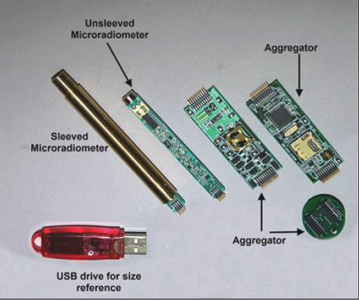 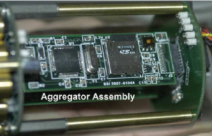 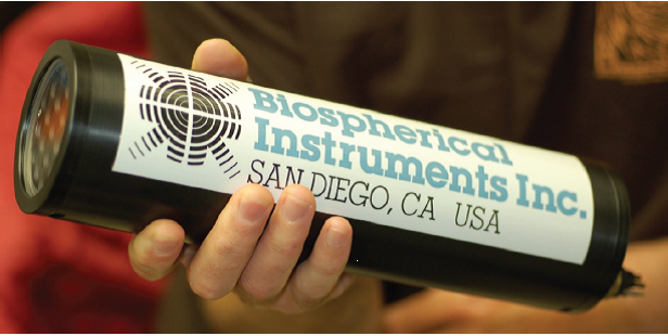 | |
 |  |  |
C-opsIntroduction to the microradiometer used
Each microradiometer has its own complete control and data acquisition system: microprocessor, 24-bit data converter (ADC), reference voltage, temperature sensor and front-end electrometer.The electrometer combines three gain stages to control the current-voltage conversion.Multiple microradiometers measure radiation in different bands, are integrated into a microradiometer group, or a complete instrument, and then controlled by an electronic component called an aggregator to collect data signals from each microradiometer.All microradiometers are synchronized to ensure that data in all bands are measured at the same time.The aggregator also includes a power regulation circuit and data communication interface, and may also be equipped with a built-in data memory (micro SD-1GB) to support remote data recording.
Technical parameters
Microradiometer parameters
Ødetector:SI (13 Mom2), when ing AA (7 Mom2), or GaAsP (7 mm2)
ØPhotocurrent-voltage conversion:Electrometer amplifiers with three gain stages: 1, 200 and 40,000
ØAnalog-to-digital converter (ADC):24-bit bipolar, 4-125Hz data frequency
ØDynamic range (available):9 decimal orders of magnitude
ØLinear:Use an adjustable light source with a signal current range of 1 x 10-12- 1 small10-5All microradiometers are measured under conditions.Typically, the error is <1% compared to a reference electrometer
Øspeed:The ADC sampling rate can be adjusted from 4-125 Hz, usually set to 125 Hz, averaged over each sampling period
ØResponse time:Less than 0.01 s, the time required for gain change is less than 0.1 s
ØElectronic sensitivity:Current resolution <10-15In the case of the ADC resolution is 0.5withoutA.Saturation current is 160withoutA.The range of the third-level gain signal is 1.6 x 10¹¹, defined as a saturated signal divided by the smallest resolved signal.
Ønoise:When the ADC samples at a frequency of 125 Hz and the built-in microradiometer averages every 25 samples, the data frequency is 5 Hz, and the detector noise is 15-20 fA.
ØOptical sensitivity:This sensitivity depends on the spectral range and incident optical system (luminance and irradiance).It is expressed as radiant (withoutW Silence-2So-1Although-1) and irradiance (withoutW Silence-2So-1).Noise Equivalent Signals at 5 Hz data frequency:
aisle | Radiance | Irradiance |
320 So | 2.9 small 10-6 | 9.0 small 10-5 |
395 So | 5.0 small 10-6 | 6.9 small 10-5 |
490 So | 1.8 small 10-6 | 2.3 small 10-5 |
683 So | 9.9 small 10-7 | 1.1 Small 10-5 |
780 So | 6.8 small 10-7 | 8.0 small 10-6 |
Note: The radiance sensor has been calibrated for underwater use.It should also be noted that the radiance sensor can point directly to the sun without being saturated.
ØDark Compensation:Dark compensation values are measured and set when calibrating for each gain level.Compensation values in the field are also automatically measured and applied to adapt to different temperatures.
ØMicro Radiometer Power Supply: 5 V DC, 4 mA
ØOptical filter:10 nm full width
ØSpectral range:250-1650 nm (InGaAs detector is required for the spectral range of 1100-1650)
C-opsSystem parameters
Øsize:The system consisting of 13 or 19 microradiometers of different bands is installed in a protective cover, and the following parameters are suitable for 19-channel sensors:
youdiameter:2.75 inches (approximately 7 cm)
youApplication depth:Standard type up to 125 m water depth, and there are 300 m water depth versions to choose from
youWavelength selection:The wavelength can be selected from 250-1650 nm
Øspeed:A separate 19-band optical instrument can operate at frequencies above 30 Hz.The operating frequency of the complete system including 3 19-band radiometers can be greater than 15 Hz.
ØData frequency:Under the conditions of using RS232 or RS485, the communication frequency of the optical instrument is 115,200 baud; under the conditions of using RS232, the communication frequency of the deck unit is 115,200 baud.
ØPower requirements:19-channel optical instrument: 7.5 V, 90 mA.Three instruments 19-channel system: Deck unit requires 0.30 A current.
ØThe field of view of the radiant instrument:In water, half angle 7°
ØCosine Error for Irradiance Instrument:±3% if the zenith angle is less than 60°; ±5% if the zenith angle is 60-70°; ±10% if the zenith angle is 70-80°.
ØFree fall speed:Depth resolution of <1 cm, adjustable final speed of 6-35 cm/s, manually adjustable inclination and tumble.
ØAuxiliary sensor:Water temperature, water pressure, inclination and rolling
ØOptional accessories:
youBioShade: a reference sensor for measuring diffuse shadow tape accessories, a reference sensor for measuring irradiance on water
youBioGPS: GPS Accessories
youUser-defined length cables, cable reels
Attachment introduction
bio shade
BioSHADE is a tape accessory used on C-OPS water surface reference sensor.This accessory can be rotated 180 degrees, allowing it to be used on unstable ships.When used on a ship, the shadow belt performs a smooth and continuous scanning; when operated on land, the system can be set to move the shadow belt directly to the sun and accordingly to measure diffuse irradiance.
The software that operates C-OPS also includes commands to control BioSHADE. Users can turn on or off the tape function in the software, or set the speed of motion.When using a ship for voyage measurements, the built-in pitch and roll sensors and high sampling frequency are very useful in eliminating the impact of hull motion.
bio shadeInstalled on the water reference sensor with BioGPS |
bio shadeInstalled on a boat |
BioSHADE can be integrated in a C-OPS network with Bio GPS, one or more surface reference sensors.This entire integration is connected by a cable to the system control unit "deckbox" and power supply at a distance (up to 150m).Deckbox will automatically compensate according to the cable length to provide the system with the best power supply.
bio GPS BioGPS (the white cylinder on the leftmost left of the picture) is a GPS signal receiver fixed to the C-OPS water reference sensor.The GPS data is combined with the C-OPS data, so that users can accurately record the position of the measurement point whether in fixed-point vertical section measurement or on board a boat.BioGPS can be integrated in a C-OPS network with BioSHADE, one or more surface reference sensors. This entire integration is connected by a cable to the system control unit "deck box" and power supply at a distance (up to 150m).The Deck box will automatically compensate according to the cable length to provide the system with the optimal power supply. |
bio GPSInstalled on the water surface reference sensor |
C-hoist C-hoistA crane is a device for lowering and recycling instruments, which is usually hung on a boom fixed to a boat to operate. C-hoistIt is equipped with a stainless steel pulley and a 2.1 horsepower, 12 V DC-driven motor head.Its total bearing capacity is 300 pounds (about 136 kg).This device is usually powered by a 90 Ah lead-acid battery, and under normal circumstances, it can complete 25 operations (about 6 minutes each) on a single charge.The diameter of the applicable rope is 5-20 mm, and there is no length limit. C-hoistWorks with a control unit (deck box) that allows users to use unstoppable de-release speeds in different layouts.The electric motor also has a brake function, so the user can keep the pulleys stationary whenever they need it. |
C-hoistThe instruments are laid out from the ship |
T-mast
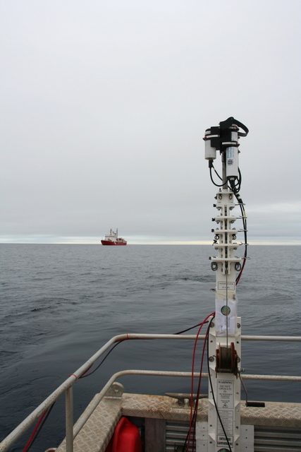
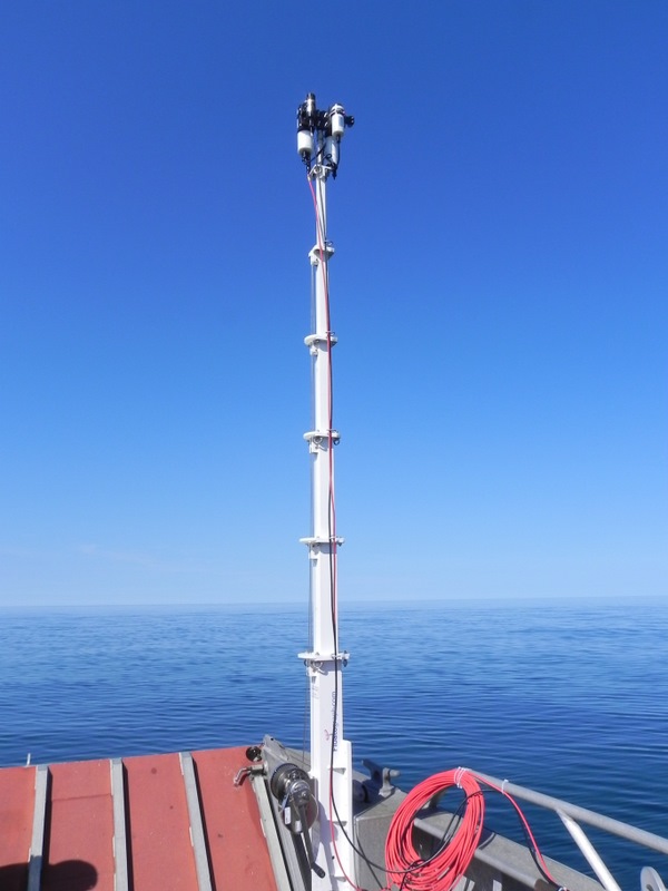
T-MAST telescopic bracket for water surface reference sensor system.The telescopic length is from 1.12 m to 3 m.This system was developed by NASA in the United States, and with its help, users can raise the radiometer above the high-level structure of the ship, thereby eliminating the impact of hull shadows and reflections.
T-mastFolding state |
T-mastFully expanded state |
BS iSome typical users in scientific research systems and government departments
ComeNASA(NASA)
ComeNOAA(US Ocean and Atmospheric Administration)
ComeUS EPA(US Environmental Protection Agency)
Comewoods hole oceanographic institution (WHO i, Woods Hole Institute of Oceanography)
ComeMonterey bay aquarium research institute (MBA RI, Monterey Ocean Institute)
Come
Comeworld meteorological organization
ComeYaleuniversity
Comeuniversityof California, Berkeley
Comeuniversity of California, Davis
Comeuniversity of California, Irvine
ComeUniversity of California, Riverside
ComeUniversity of California, Santa Barbara
Comeuniversity of California, San Diego
ComeStanforduniversity
Comeuniversityof Chicago
ComeMassachusetts institute of technology
ComeArizonastate university
ComeAustralian Antarctic division
ComeAustralian institute of Marine sciences
ComeBedford institute of oceanography
ComeBigelow laboratory for ocean science
ComeBostonuniversityMarine program
Comebowling greenstate university
ComeBritish Antarctic survey
Comecenter for coastal physical oceanography
ComeVirginia’Double center for innovative technology
ComeFrench governmental research agency
Comecent red’ocean OL o Goethe Marseille, Lumi NY of campus
ComeColorado state university
Comeuniversity of Copenhagen
ComeCalifornia state university, long beach
ComeCalifornia state university, San Marcos
ComeDanish meteorological institute
Comenational environmental research institute,
ComeDukeuniversity
ComeFloridagulf coast university
ComeFinnish institute of Marine research
ComeFloridastate university
Comeuniversityof Georgia
ComeGoteborguniversity
ComeHawaii institute of Marine biology, so EST
Comehong Konguniversityof science and technology
ComePolishacademyof sciences
Comeuniversityof Maine
Comeuniversityof Maryland
Comemax-Planck-INS TE TUT Madam Marine MI Cool Rob IO log IE
ComeUN VIE RSI TYMichigan
Comeuniversity of Minnesota
Comeuniversity of Mississippi
ComeMoss landing Marine labs
ComeMichigan state university
Come on <span style="font
