| Instrument features |  | ||||||||
ØUltra-low power design ØSupports vibrating sensor ØSupports Carlson, photoelectric level and LVDT displacement sensors ØScalable up to 960 analog channels | |||||||||
| Software Features | |||||||||
ØBuilt-in software without installation and can be used on Windows, Mac and Linux operating systems ØThe instrument is set up through the web page ØConnect to the instrument through network cable and USB data cable ØIntuitive graphical interface ØSimple setting interface for users of all levels ØReal-time and historical data can be viewed ØYou can display data with icons, bar charts, dials, and waveform charts | |||||||||
Application areas | |||||||||
| Landslide treatment, dam wall monitoring, underground continuous wall monitoring, mining exploration, tunnel excavation, pile monitoring, etc. | |||||||||
| System Introduction | |||||||||
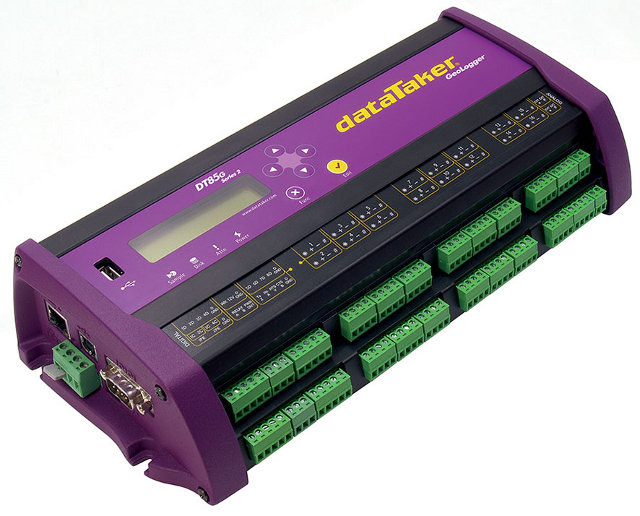
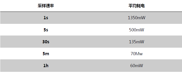
Display and keys Type: LCD display, 2 lines 16 characters, background light; Display functions: channel data, alarm information, system status; Key: View display information and operation functions through 6 keys; Signal LED lights: 4 signal lights, indicating sampling, hard disk, alarm information and power supply respectively; Software version upgrade Software upgrade through RS232, network cable, USB or USB drive; clock Basic resolution: 200µs; Accuracy: ±1 min per year (in an environment with a value of 40 ℃), ±4 min per year (in an environment with a value of -40 ℃ to 0 ℃, 40 ℃ to 70 ℃); powered by External power supply range: 10 to 30Vdc; Built-in power supply: 6Vdc 4Ahr lithium battery; Peak power: 12W (12Vdc 1A); Average power loss The relationship between sampling frequency and power consumption when using 12Vdc external power supply is as follows:
The relationship between the sampling frequency and host usage time when using the built-in 6Vdc 4Ahr lithium battery is as follows:
Basic Features Digital shell: zinc-aluminum alloy; Ruler Inch: 300 x 137 x 65mm; Weight Quantity: 2.5kg; Operating temperature: -40℃ to 70℃; Operating humidity: 85%, water vapor does not condense; Note: Low and high temperature environments will reduce battery life, and the operating temperature of the LCD display is -15℃ to 50℃. | |||||||||
Simulation channel | |||||||||
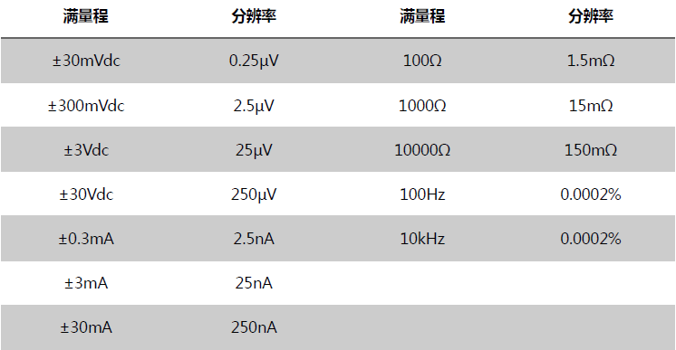
The DT85G has 16 analog channels, which can be expanded to up to 320 analog channels. Each analog channel can be connected to a three-wire or four-wire input, two independent two-wire inputs, and three two-wire single-ended inputs. The specific number of accesses is as follows: Two-wire single-ended channels: 48 (up to 960 expansion); Two-wire differential channels: 32 (up to 640 expansion); Three-wire or four-wire differential channels: 16 (up to 320 expansion); Note: The extension requires the configuration of the CEM20 module, which contains 20 analog channels. Basic input range The basic input voltage, current, resistance and frequency range that the DT85G can measure is as follows:
Note: The data collector has the function of automatically changing the range and can be switched within three ranges. The basic input voltage, current, resistance and frequency accuracy that the DT85G can measure is as follows:
Note: Accuracy is relative to full scale. Sampling information For measurement accuracy and suppression of the effects of noise, a row frequency period greater than 50/60Hz is integrated. Maximum sampling speed: 25Hz; Effective resolution: 18 bits; Linearity: 0.01%; Common mode suppression: >90dB; WireSexual chain mode suppression: >35dB. enter Channel isolation: 100V (relay on); Isolation of analog components: 100V (optical isolation); Input impedance: 100KΩ, >100MΩ; Common mode range: ±3.5V, or ±35V in the 30V range. Sensor excitation Analog channel excitation: 250µA or 2.5mA precision current source, 4.5V voltage, can switch external power supply; General Excitation: Can turn on and close 12V power supply (maximum 150mA) to power sensors and accessories, and can turn on and close 5V power supply (maximum 25mA) to power analog channels. | |||||||||
| Analog sensors | |||||||||
Several common sensors are introduced, but the sensors that the DT80G can connect to are not limited to the following types. Thermocouple Thermocouple types: B, C, D, E, G, J, K, N, R, S, T-type; Thermocouple calibration: ITS-90; RT DS RTDs material types: Pt, Ni, Cu; Resistance range: 10Ω to 10KΩ; Vibration line Frequency range: 500 to 5KHz; Coil resistance: 50 to 200Ω; Simulation method: single pulse pluck; Thermistor Thermistor type: YSI400xx series; Resistance range: <10kΩ Note 1: Other thermistor types are also supported. Note 2: The measurement range can be expanded by parallel resistance. Single-chip temperature sensor Support types: LM34-60, AD590\592, TMPxx, LM135\235\335; Strainer and bridge sensor Configuration: 1/4 bridge, 1/2 bridge and full bridge; Excitation: voltage or current; Carlsonsensor Inline stress and temperature functions; 4-20MACurrent ring Internal 100Ω or external shunt resistor. | |||||||||
Digital Channel | |||||||||
Digital input/output 8 two-way channels Input type: 8 logic levels (maximum 20/30V); Output type: 4 field effect transistors (maximum: 30V, 100mA), 4 logic outputs; Relay output 1 direct-connected self-locking relay (maximum: 30Vdc, 1A). | |||||||||
Counting channel | |||||||||
Low speed counting 8-channel counter, shared with digital channels; low-speed counting function does not work in sleep mode. Model: 32bit; Maximum counting rate: 10Hz; Special counting input 4 high speed or 2 phase encoder inputs Model: 32bit; Maximum counting rate: 100kHz; Input type: 2 logic level inputs (maximum ±30V). 2 magnetic induction (maximum ±10V) sensitivity inputs (10mV). | |||||||||
Serial Channel | |||||||||
SDI-12 There are four SDI-12 channels shared with digital channels, and each SDI-12 channel can be connected to many SDI-12 sensors; Universal serial sensor It can easily record data in sensors and data streams. Available ports: serial sensor port (RS232, RS422, RS485) or host RS232 port; Baud rate: 300 to 115200. Note: When using the serial sensor channel, the host port is not available for communication. | |||||||||
Compute channel | |||||||||
| Conditions: below, above, within or outside the range; Delay: optional alarm response time; Action: Digital output, pass information or execute any datataker command. | |||||||||
Data collection list | |||||||||
| Number of schedules: maximum 11; Schedule sampling interval: Each schedule has a separate sampling interval, which can be selected from 10ms to days. | |||||||||
Data storage | |||||||||
Built-in storage Storage space: 128MB, about 10,000,000 data can be stored (large space memory can be customized); External storage device USB1.1, USB2.0 and other USB flash memory devices. | |||||||||
Communication panel | |||||||||
Network cable port Panel: 10Mbps; Protocol: TCP/IP, Modbus protocol; USBport Panel: USB1.1 (virtual communication interface); Protocol: ASCII command; Host RS232 port Speed: 300 to 115200 baud rate (default 57600); Flow control: Hardware (RTS/CTS); Software (XON/XOFF): None Handshake protocol: DCD, DSR, DTR, RTS, CTS; Modem supports: automatic answering and dialing; Protocol: ASCII command, TCP/IP (PPP), Modbus protocol, serial sensor; Serial sensor port Panels: RS232, RS422m, RS485; Speed: 300 to 57600 baud rate; Flow control: Hardware (RTS/CTS); Software (XON/XOFF): None Handshake protocol: DCD, DSR, DTR, RTS, CTS; Protocol: Modbus protocol, serial sensor; | |||||||||
| Network Services (TCP/IP) | |||||||||
| Use network cable port or host RS232 port Command panel: Enter the ASCII command panel of DT80G through TCP/IP; Network server: access the status of existing data and data acquisition through web pages, set the user's characteristic display interface, and download CSV format data; Modbus server (controlled end): obtain data and data acquisition status through the Modbus client; Modbus client (main control): read data from the modbus device or write data to the modbus device; FTP server: Obtain stored data through a browser or FTP client; FTP client: Automatically download data to the FTP server. | |||||||||


